Products
MODERN TOOLS, INC. provides manufacturing solutions with exclusive representation of the following machine tool technologies.
Coolant Filtration Systems
Filtrations systems offer tailor-made solutions and serve the Automotive, Aircraft, Aerospace, Defense, Medical and Bearing manufacturing markets with a complete range of central coolant filtration systems, auxiliary equipment, swarf handling systems or stand alone coolant filters for the individual CNC machine tools.
Coolant Filtration Systems are designed for the application and the specific machine tool they are being added to. These systems provide filtered coolant to the machine tool it is connected to the entire time the machine is in operation. For example, a coolant filtration system that is added to a CNC Tool and Cutter Grinding machine that is grinding Carbide End Mills, will filter the ground carbide particles out of the coolant and then the clean coolant will be delivered from the filtration system to the Grind Zone to aid in the Grinding Process. Coolant Filtration Systems are added to all Machine Tools that require Coolant in their Manufacturing Operations, such as but, not limited to, Grinding, Milling, Turning, Broaching machines and many others.
Central Coolant Filtration Systems:
Central Coolant Filtration Systems:
Swarf Handling:
This computer numerically controlled (CNC) grinding machine has all of the capabilities of a CNC cylindrical grinding machine, with the added feature of a Universal (Swivelable) Wheelhead. This type of wheelhead usually swivels 180º (either manually or automatically) and utilizes three separate wheel types.
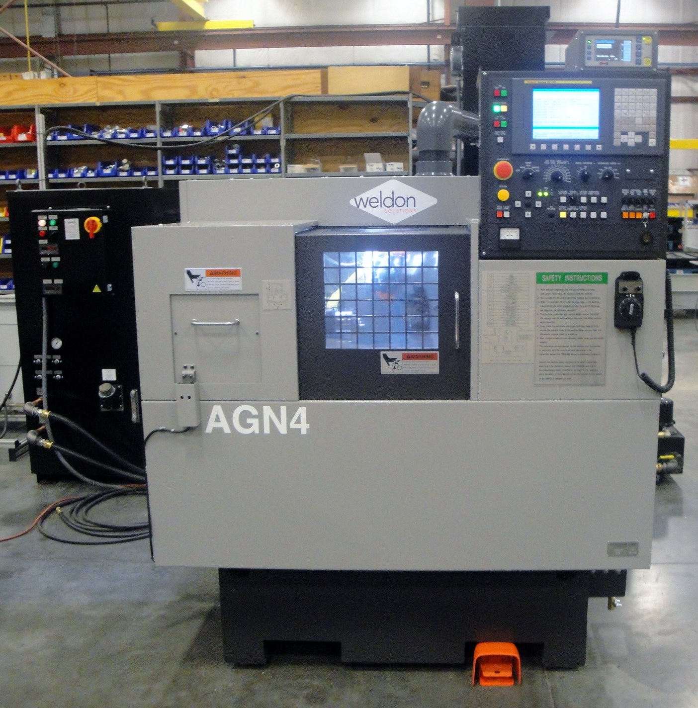
The cylindrical grinding wheel is located on the left hand side of the wheelhead and can be used as a straight infeed grind or adjusted for an angle (usually set at 30º to the workpiece) to grind a diameter and adjacent face, simultaneously. A facing wheel is located on the right hand side of the wheelhead and can be positioned or swung into an angle, such as 90º to the workpiece to face grind a flange surface or a workpiece shoulder. The third wheel on a universal grinding machine is the internal grinding wheel and is usually mounted on the back of the wheelhead and is swung into position by rotating the wheelhead 180º to the workpiece. This wheel is used to grind internal bores or diameters in a particular workpiece, thus giving you the ability to grind both external and internal workpiece features on a single machine, hence the name, "universal grinding machine."
Air Filtration is a broad topic for Industrial Applications. Simply put, this covers all environmental needs in a shop factory to keep the air clean in the entire shop as well as to keep each machine tools mist, dust, and odor from reaching the machine generator and the shop air environment.
Mist elimination is also a major use of these machines.
This category also includes Air Conditioning of shop factories and solutions for workpiece cleaning and marking.
A computer numerically controlled (CNC) cylindrical grinding machine performs the function of removing a small amount of material, usually .005" to .025", from a cylindrical component to bring it to its final configuration.
A cylindrical grinding machine operates between two workpiece center holes, from a workhead driven chucking device or from a collet fixture.
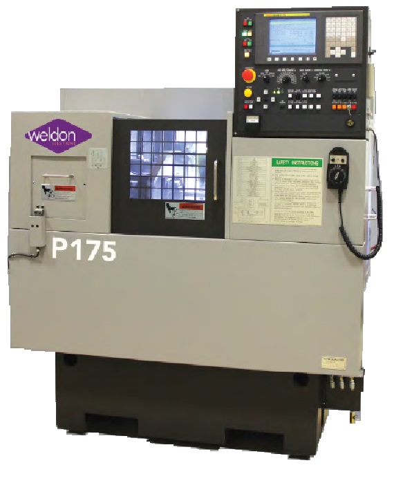
The cylindrical grinding machine is driven by a computer system allowing you to develop and save workpiece programs for both the grinding operation and the wheel dressing function. These programs can be generated either at the cylindrical grinding machine or from a remote workstation and saved for repeat usage.
The CNC Cylindrical Grinder can be programmed to grind more than one feature of a particular workpiece in a single grinding operation. For example, geometry permitting, a CNC cylindrical grinding machine can grind several different workpiece diameters, each with different corner radii, including tapered and angled diameters, in one operation. This allows for fewer set-ups and change-overs as on manual machines, creating fast cycle times, increased thru put and tremendous potential cost savings. The cylindrical grinding machine is used for small lot sizes and production lot sizes.
A computer numerically controlled (CNC) surface grinding machine is utilized to finish grind flat workpieces to a final configuration, automatically. The workpiece is typically mounted to the horizontal worktable and held down by either a magnetic chucking device or a workpiece specific clamping fixture.
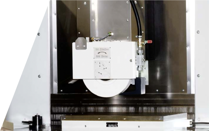
The worktable on a surface grinding machine can be programmed to move both laterally and in a cross feed direction either front to back or vice versa. The wheel spindle is also mounted horizontally and its downfeed can be programmed as well. On a surface grinding machine, all three motions; lateral and crossfeed table movements and wheel downfeed movement can be programmed to move either simultaneously or in sequence to finish grind a workpiece to the required configuration.
As with most types of CNC grinding machines, the wheel dressing sub- routine on a surface grinding machine can also be programmed to automatically dress (recondition) the grinding wheel and readjust its location to compensate for wheel wear and wheel dressing amounts.
The entire grinding and dressing program can be saved on a surface grinding machine's storage system or offloaded onto a disk for permanent storage and for future use. A surface grinding machine is usually best suited for small lot sizes and production lot sizes of repeat grinding jobs.
A computer numerically controlled (CNC) creep feed grinding machine is used to remove large amounts of material off workpieces in a single pass or in several passes to profile a shape to finish dimensions. The creep feed grinding machine has a horizontal table that has a lateral and crossfeed movement. The wheel is attached to a horizontal spindle, similar to a conventional surface grinding machine. The creep feed grinding machine is also equipped with a CNC wheel dressing device that can be arranged as a wheel profiling system or a diamond roll system.
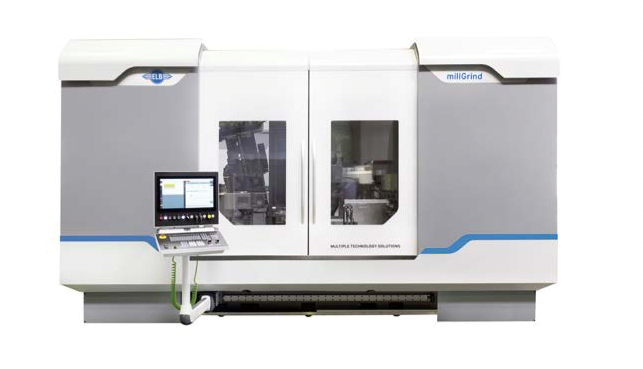
The wheel profiling system can be programmed to generate the desired wheel geometry and the diamond roll system utilizes a diamond roll that is configured to the shape needed in the wheel to plunge this shape into the wheel in a single plunge.
Creep feed grinding machines are most commonly used to grind a shape or profile into a hardened workpiece, from a pre-machined blank, to finish dimensions, thus eliminating the milling and/or turning operations that are usually done prior to the grinding operations.
The typical uses of a creep feed grinding machine is to grind a shape or profile into a tough- to- machine material, after it is heat treated. This process saves time and eliminates operations and also can give you a better workpiece as opposed to the conventional process of, milling or turning, then heat treating then finish grinding.
A creep feed grinding machine is usually used in medium to high volume workpiece production.
A computer numerically controlled (CNC) tool and cutter grinding machine is used to grind all types of cutting tools (drills, endmills, reamers, taps, etc.) to final dimensions, from a solid blank. Tool and cutter grinding machines are also used to regrind tools that have been used and are dull to restore them to their original dimensions so they can be used again.
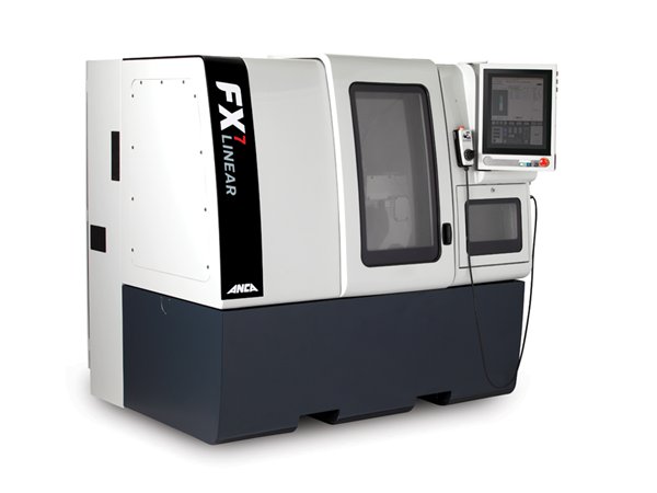
When you are producing new tools or regrinding drill tools, a tool and cutter grinding machine is very useful to make one tool or a series of tools that are exactly the same and will give you longer, more accurate cutting capability for a longer lifetime.
Tool and Cutter grinding machines utilize very powerful grinding programs which allow you to develop a tool program from very simple menu pages and can be used with carbide or steel materials.
CNC Tool and Cutter Grinding machines can also be configured with workpiece loading devices, wheel dressing devices, and wheel changing devices to grind one piece lot sizes up to production lot sizes and then can be set up and changed over to different grinding jobs easily and rapidly.
These computer numerically controlled (CNC) punch grinding machines are designed to grind non-round workpiece configurations form a solid blank workpiece billet. This type of grinding machine holds the pre-ground workpiece in a workhead chuck or collet clamping system located on the table of the machine.

The CNC control can be easily programmed to generate the desired shape. Once the program is completed, the machine will synchronize the rotation of the workpiece; the tables lateral movement and the in-feed of the grinding wheel in the most efficient sequence to remove the grind stock quickly and accurately.
Therefore, with this machine tool, very accurate punches and non-round dies and various other components that require a non-round configuration can be produced, from solid, very efficiently. Also, once the punches or non-round components are produced and used in the intended application, they can be re-ground and used for other smaller punch or non-round application, reducing overall workpiece costs and scrap rates. These machines usually are best utilized in small to large lot sizes.
This computer numerically controlled (CNC) grinding machine performs the function of grinding a round or flat, blank workpiece into a formed tool to very precise tolerances.
This type of machine utilizes a wheelhead that pivots so that the grinding wheel can contact the workpiece in the same spot througout the grinding process.
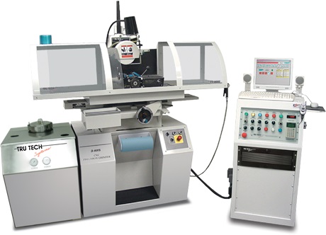
This allows one to keep a very accurately honed grinding wheel in contact with the grind process which results in a very precise and controlled grinding environment.
The CNC Profile Grinder can be programmed using a menu-driven Software package that makes it easy to program complex shapes, including angles, tapers, various radii and straights. You can also directly download CAD files into the machine software programs that minimizes your programming time to a basic minimum.
Deburring is the process of removing a burr or a rough edge on a machined component. In turning, milling and high speed grinding, often times a burr is generated from the tool being used to shape the component. Removing burrs from parts or deburring parts is a very delicate operation because, if not done correctly, the burr can scratch or mark your machined component making it a scraped part.
Deburring machines can be designed and built for specific applications. Some deburring machines are designed and built to deburr the same component, in a high production environment and can run entirely unattended.
Other deburring machines are designed to debur a multitude of various components in a small lot, tool room environment.
Deburring is usually considered a stand alone process and the machine that is purchased for this process is usually custom designed and built.
Edge prep is the process of customizing the cutting edge of a cutting tools, such as drills, endmills, taps, reamers, hobs and most other round tools with a cutting edge. In customizing your cutting tool “cutting edge” you can make the cutting edge cut more freely, last longer and cut more accurately. The edge prep process can be performed in a low volume, small lot process or set up as a production process, robotically controlled for dedicated, high volume manufacturing.
Super Abrasive Machining equipment is designed to remove large amounts of material in a short period of time. Super Abrasive Grinding machines can be configured to machine flat parts off of a table fixture with a horizontal spindle wheelhead or round, cylindrically shaped parts either between work centers or chucked in a workhead holding device.
Super Abrasive Grinding Machine can utilize either pre-shaped vitrified CBN (cubic boron nitride) grinding wheels or dressable grinding wheels.
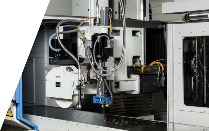
The process for a Super Abrasive Grinding Machine is to remove metal utilizing high wheel speeds and full profile depths of cutting with very high pressure coolant precisely directed into the grinding zone.
The result of this process is to remove large amounts of material with quick cycle times in difficult to machine materials, oftentimes eliminating milling and turning operations. All after the workpiece has been heat treated.
-A Super Abrasive Grinding Machine is most suited for dedicated, high volume workpiece lot sizes or similar workpiece family configurations.
These machines are conventional, usually hydraulically operated grinding machines that are used to grind small lot sizes and many times, one piece lot sizes.
Cylindrical tool room grinding machines can be setup to grind round parts, either between workpiece centers or from a workhead driven chucking or collet system.
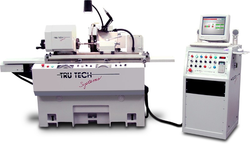
These machines are usually very versatile to grind straight diameters, tapered diameters, shoulders and faces on workpiece parts.
Surface grinding tool room machines are typically equipped with a standard table mounted magnetic chuck with a hydraulically controlled and driven table and wheelhead.
Internal toolroom grinding machines are capable of grinding internal features of a particular workpiece, one at a time. The wheel grinding spindle is hydraulically controlled and can be arranged to remove a certain amount of material on a specific workpiece bore. The workhead can be arranged with a chuck, collet system or workholding faceplate to hold and drive the workpiece while it is being ground.
All of these machine types are usually hydraulically driven or driven with a simple, microprocessor driven feed system. They are controlled by the machine operator to perform the actual grinding operations and require skill and training to perform the grinding operations to the required configurations. Typically, all manufacturing operations have a toolroom machine to accomplish its task.
These machines are designed to utilize either a computer numerical control (CNC) or a dedicated production style, microprocessor control. These machines are designed to finish grind two sides of a flat component at the same time to an overall width dimension using two separate grinding wheels.
Depending on the workpiece configuration, the workpiece can either be ground utilizing two horizontally opposed grinding wheels or two vertically opposed grinding wheels.
Depending on the workpiece configuration, the workpiece can either be ground utilizing two horizontally opposed grinding wheels or two vertically opposed grinding wheels.
These machines are usually set-up to run large lot sizes of one workpiece type or a family of similar workpieces. However, utilizing the flexibility built into a CNC controlled machine, a machine can be configured to grind various, dissimilar parts in smaller lot sizes.
Automatic loading and unloading systems are often applied to double disc grinding machines with workpiece sorting and stacking devices allowing for an operator-free production station and high levels of output.
Centerless Grinding Machines can be either computer numerically controlled (CNC), microprocessor controlled, or controlled conventionally via manually actuated hydraulic controls. These machines are designed to grind round workpieces without workpiece center holes or holding devices.
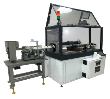
The workpiece is held or balanced on a workrest blade device and either fed through two opposed wheels, one grinding wheel for stock removal and one regulating wheel for workpiece rotation and support, or plunged infeed and then ejected out of the grinding zone.
The thrufeed process is used to grind a workpiece outer diameter (OD) by passing it through the two wheels, driven by the regulating wheel, adjusted to a feed angle. This is often a high production operation utilizing automatic loading and unloading devices.
The infeed process is a plunge grind operation where a workpiece with a profile can be plunge or in-feed ground to finish dimensions and ejected to the unload zone. It is also quite common to utilize automatic loading and unloading devices with this type of centerless grinding machine.
Gaging systems are most commonly used on grinding machines to monitor the grinding operation and take control of it to assure that the grinding machine grinds the workpiece to its pre-programmed or preset final dimension.
In the grinding operation, the grinding wheel wears and gets clogged up with grinding particles (grinding swarf) causing the machine to grind over or under the pre-determined dimension. The gaging system can monitor this situation and override the grinding program to allow the machine to grind to the pre-determined grind tolerance or dimensions.
In-Process gaging is performed during the actual grinding operation and takes over control of the grinding operation and will only allow the machine to stop grinding when it has come to its final dimensions, even if the grinding wheel has become dull or broken down.
Post-Process gaging is performed after the grinding of each workpiece. At that point, a measurement is taken and if a correction or compensation is needed to adjust the machine so that the next part will be ground closer to mean of the pre-programmed upper and lower grinding limits, it is done automatically.
Gaging systems can also be utilized on Hand Turning Machines and Superfinishing Machines to assist in process control of each particular operation.
A Wheel Truer/Dresser Machine is a machine tool that can be used to form a shape in a grinding wheel for a particular grinding operation. These machines have a Programming system and an Optic system to assist the operator in shaping or reshaping a grinding wheel or wheels that are mounted on their specific grinding spindle. A Wheel Truer/Dresser allows the user to condition, shape, or clean a grinding wheel or wheel pack very accurately and repeatedly to ensure consistent grinding results.
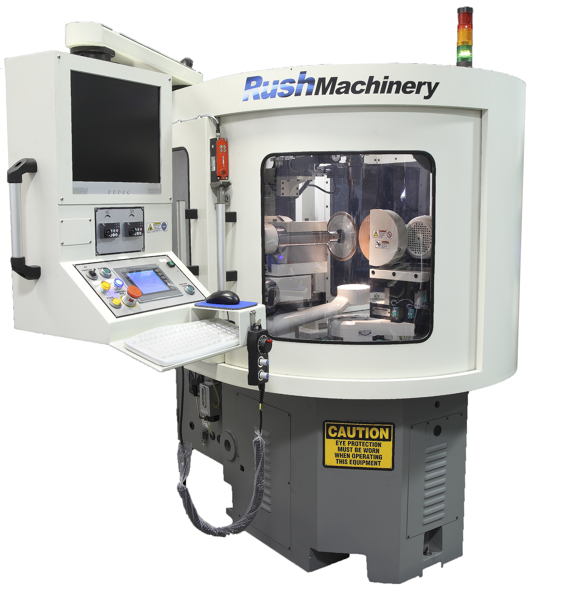
These computer numerically controlled (CNC) jig grinding machines are most commonly used to finish grind different size bores or holes in a flat workpiece in any pattern or in any sequence. The workpiece is usually horizontally mounted on the machine and the grinding spindle is usually arranged vertically. This type of machine can be programmed to precisely grind a multitude of holes in a random pattern in relationship to one another. Programs can be generated at the machine or at a remote station and saved for future use.
